使用GraphEdit執行 Camera 720p -> MJPEG Decode -> H.264 Encoder -> FFMPEG Decoder -> Render,觀察CPU約90%,21 FPS
↧
N4200 進行Camera 測試 時, CPU 使用率90% , 21FPS
↧
I210 - Packet loss issues
HI ,
we have used I210 Pcie to Gigabit controller on our board & have followed all the schematics reference and routing guidelines as suggested by intel .
we have also programmed the EEPROM & have detected the Ethernet controller with 1G Link .
we are having high packet loss issues around 35% when transmiting data on this port .
what could be possible area to looked at ?
Thanks in advance.
Murugan
↧
↧
Harcuvar (Denverton processor) - spsFPT / Intel ME FW kit location
I need to update FW BIOS of Harcuvar EDK platform. I already have access to the updated BIOS file (HVLRCRB.86B.B.64.2017.35.4.01.0404.HCV15D62.bin). Reading the "Harcuvar Platform CRB User Guide rev 2.3" and the document "Denverton SoC Product Family SPI Flash Programming" I see that I also need an updated flash programming tool (FPT) which is part of Intel ME FW Kit.
However I cannot find the Intel ME Firmware kit for Harrisonville (Cormorant Lake). I checked https://platformsw.intel.com and also alll the collateral available for Denverton/Denverton-NS (https://tigris.intel.com/scripts-edk/viewer/UI_UpdateDesignKits.asp?edkID=11381&ProdID=45343&CatID=0). Could anyone advise the correct place to find the Intel ME FW Kit including spsFPT.efi tool?
Thanks.
↧
I210 test 100BASE-TX find failed item on "UTP Vout Differential Output Voltage"
Hi,
We use Springville I210 ethernet controller, test Ethernet 100BASE-TX find failed item on "UTP +Vout Differential Output Voltage"
Did anyone have any suggestion to tune it or to solve it?
Fail item:
Test |
| Measure Value | Result |
Output Voltage(+Vout) | 950mV to 1050mV | 1.0654 V | Fail |
Output Voltage(-Vout) | -950mV to -1050mV | -1.0867 V | Fail |
Many thanks!
↧
[Apollo lake] There is some garbage words shown in Windows10.
Hi,
My project has Graphics issue.
Apollo lake SOC : N4200
Windows 10 Enterprise version : 1703
Intel® Graphics Drivers :15.45.19.4678
- Log in Win10 and click windows start logo then you can see some garbage words shown in Windows menu.

Please kindly help us to solve this problem.
Thanks
Best Regards,
Robert
↧
↧
Route I2S Signals to Headers on GLK RVP
Hi,
Now, I have a rework issue about routing i2s signals to pitch headers on GLK RVP.
My device is RVP2.
From document #570726 "Gemini Lake Platform Customer Reference Board Rework Notes User Guide Rev 0.92",
I don't see any introduction about materials required to perform rework on RVP2, it just only have RVP1 introduction from page 138~143.
However, I also see the Feature Rework of notes is applicable to RVP1 and RVP2, does the notes lose related introduction of materials required on GLK RVP2?
BRs,
David
↧
Some questions about Microsoft Windows* 10 64-bit GPIO Driver for IOTG Apollo Lake Platforms
Hello,
Our platform is Intel Apollo Lake and we installed Intel_Atom_E3900_Processor_Win10_RS1_GPIO_Driver_Gold on win 10.
Q1: The release note,569071_Win10_GPIO_Driver_Gold_Release_Notes_Rev1.1.pdf, shows the driver can support GpioClx DDI. Does it mean we can set gpio pin as input, output or interrupt ? If yes, could you tell us how to use it in detail ?
Q2: Can we just use ioctl of the driver to set gpio pin as input, output or interrupt ? If yes, could you tell us how to use it in detail ?
Best Regards,
↧
White Paper: Intel Xeon Processor Family Choice for Embedded Solutions Processor Impacts SWaP-C, Overall Complexity and Reliability
 Defense application requirements are broad and often mission environments are extreme. Leveraging Commercial Off the Shelf (COTS) technologies, and in particular Intel® Xeon® server class multi-core processing engines, provides solution designers myriad options for a wide range of application implementations. Time proven embedded system engineering design practices confirm that meeting requirements by creating designs with reduced complexity ultimately result in higher reliability, better quality and lower overall life cycle costs. The designer’s choice of Xeon family processor type, a XEON E5 or the XEON D System on Chip (SoC) device, can have has wide reaching impact to size, weight, power and cost (SWaP-C), module and sub-system complexity and overall reliability.
This white paper by Curtiss-Wright identifies many considerations and trade-offs that are critical to consider before a Xeon processor type is chosen. It identifies module and subsystem impacts based on the selection process identifying why the selection decision should not be made purely on TFLOPS/slot but rather overall architectural sub-system optimization. Curtiss-Wright CHAMP-XD OpenVPX family of products based on the Xeon-D are then identified and SWaP-C characteristics highlighted. Conclusions are summarized identifying the considerations and solution impact of processor type selection for current and next generation defense applications.
Download this Intel Xeon Processor Family Choice for Embedded Solutions Processor Impacts SWaP-C, Overall Complexity and Reliability white paper to learn more about
- Intel Xeon Processor family comparisons
- Processor selection criteria trade-offs
- Module design complexity considerations
- Creating balanced and high reliability solutions
- Curtiss-Wright CHAMP-XD1 3U VPX DSP Card, CHAMP-XD2 6U OpenVPX DSP Card and CHAMP-XD2M 6U OpenVPX DSP Card with high memory capacity products
↧
Video: DTS1 - Protect your Data-at-Rest

More than ever, sensitive data on unmanned platforms must be protected due to the inherent dangers associated with their missions.
Protecting that data becomes a challenging task as unmanned vehicles get smaller, limiting available space for subsystems.
Bulky data protection systems tend to take up more space, add more weight and cause more fuel to be consumed…dramatically shortening mission duration time.
And while unmanned vehicles are shrinking, the costs associated with data protection are constantly rising.
The Curtiss-Wright DTS1 is an easy to use, turnkey, rugged network File Server based on the Intel Atom Processor that houses one Removable Memory Cartridge (RMC) that provides quick off load of data. The RMC can be easily removed from one DTS1 and installed into any other DTS1 providing full, seamless data transfer between one or more networks in separate locations. Watch the DTS1 COTS-based File Server Video.
↧
↧
White Paper: How GPGPU Performance and Programmability can power Video Mixer Display Applications in the defense and aerospace markets
 Mission display computers play an important role in an increasing number of imaging applications such as digital moving maps, 360° situational awareness, persistent surveillance, embedded training, and degraded visual environments. These systems are designed with advanced graphics capability to drive multiple displays independently with video from multiple sources. The display video can be a combination of input from multiple sensors, generated digital map video, symbology, and metadata information from a variety of other sources. All of this information is combined and overlaid to provide multiple operators each an instantaneous independent view of the battlefield.
Requirements of a mission display application are a large number of ports to handle the number of video sources, high performance and bandwidth to handle the increasing resolution of sensors and displays, low latency for immediate feedback, and flexibility to handle the variety of sensor and display interface formats. The video mixer is the heart of the mission display computer and generally required an FPGA to combine the multiple inputs into multiple display outputs. The issue with this approach was the difficulties inherent to FPGA programmability. FPGA-based video mixers were generally uniquely tailored to each platform, lacked floating-point arithmetic precision, were difficult to modify to deal with changes in video interfaces or processing requirements, and required lengthy development schedules.
Advances in embedded graphics technology make a product such as the commercial GPGPUs, with its higher performance and bandwidth, a feasible and attractive alternative to replace the FPGA as the video mixer for some mission display applications. This is further augmented by the video processing and generation capabilities of Intel’s built-in integrated graphics in their multi-core CPUs.
This white paper discusses how the combination of high performance standalone and integrated GPGPUs combine with FPGA interface flexibility to provide increased programmability and versatility to the video capabilities required of a mission display computer. The white paper includes a Curtiss-Wright embedded system featuring Intel Xeon SBCs, NVIDIA GPGPU processors and FPGAs to optimize performance.
Download this white paper to learn more about:
- Mission Display Computer
- Video Mixer
- Sensor Input Processing
- Graphical Processing Units (GPUs)
- General Purpose GPUs (GPGPUs)
- Intel Integrated GPUs
↧
Accelerate Virtual RAN Deployments with a Pre-Integrated End-to-End System Solution
Radio Access Network (RAN) terminology is nothing if not confusing. Traditional RAN configurations are now termed “Distributed RAN”. The first phase of cost optimization through consolidation is typically called “Centralized RAN” or “CRAN”. Capacity improvements achieved through baseband pooling are often known as “Cloud RAN”, representing another, different use of the term “CRAN”. Currently, the ultimate approach to enhancements is “Virtual RAN” or “vRAN”. And we haven’t even mentioned “mini-CRAN”, proposed by China Mobile, let alone “Coordinated RAN”, “Collaborative RAN”, “Clean RAN” or “Advanced CRAN”, all of which have shown up in conference presentations over the past three years.
Regardless of all these flavors of RAN improvements, there’s consensus within the industry that a virtual RAN (vRAN) architecture enables service providers to achieve the best overall potential of cost savings, dynamic capacity scaling, better Quality of Experience (QoE) and rapid instantiation of new services.
In a vRAN architecture, the Baseband Units (BBUs) are virtualized, rather than being located at the cell site as physical equipment. The virtual BBUs are deployed on NFV infrastructure software platforms like Wind River’s Titanium Cloud, running on industry-standard x86 servers and consolidated in centralized data centers, while the Remote Radio Units (RRUs) remain at the cell sites at the edge of the network. vRAN leverages standard server hardware that cost-effectively scales up or down processor, memory and I/O resources based on dynamic changes in demand, infusing the RAN with capacity for application intelligence, which significantly improves service quality and reliability. In many configurations, the architecture also allows for Ethernet and IP fronthaul transport, which gives services providers more cost-effective options for RRU connections.
To accelerate the introduction of cost-effective vRANs, Wind River has collaborated with Altiostar, Amdocs and Dell EMC to develop a pre-integrated, validated end-to-end solution, ready for deployment by service providers.
Altiostar contributed their vRAN solution, which comprises a software-intensive LTE eNodeB combined with Ethernet fronthaul. Amdocs provided their Network Cloud Service Orchestrator (NCSO), an open, catalog-driven service orchestration solution, while their professional services expertise is also available for designing, deploying, operating and optimizing mobile networks. The solution leverages the Dell EMC PowerEdge R630, an ultra-dense, two-socket 1U rack server based on the latest Intel® Xeon processor E5-2600 v4 product family. Finally, Wind River’s Titanium Cloud platform is the industry’s only fully integrated, ultra-reliable, deployment-ready family of virtualization platforms that enables service providers to deploy virtualized services faster, at lower cost and with guaranteed uptime.
You can read all about the benefits of this integrated vRAN solution in our recently-published white paper “vRAN: the Next Step in Network Transformation”.
You’ll also want to check out the recording of our recent webinar hosted by SDxCentral, where representatives from all four companies jointly presented the solution and explained the business benefits that it delivers.
By extending the benefits of network virtualization from the core to the RAN, vRAN is the optimal solution for cost-efficiently increasing capacity, reducing costs and creating new services. The solution described in the white paper and the webinar delivers carrier grade reliability, predictable performance, low latency, unrivaled manageability, massive scalability, optimized resource utilization and flexible deployment options. These best-in-class technical features provide service providers with clear, quantifiable business benefits in terms of cost reductions, capacity improvements and accelerated deployment times.
If you’d like to know more about any of the Titanium Cloud products or solutions, please check out the information online or contact us to arrange a face-to-face discussion.
↧
Romley CRB "harbor city" BMC code
We designed a board almost same as Romley CRB harbor city(E5-2640 V2), now we need harbor city BMC code for board bring up, but can't find it.
↧
XL710 Power Supply (hardware)
I'm designing power supply for XL710 with LTC3833. My reference is XL710 Reference Schematics. Could you please explain which ground connection should be used on capacitor C85 (On-Die sensing control capacitor). Is this PGND or SGND?
Intel® Ethernet Controller XL710 Reference Schematic
Best Regards Matic
↧
↧
Cannot program an I211 controller
Hello there,
I'm having issues flashing the I211 controller with the eepromARMtool. I've double checked both the HW and SW settings of my design and everything appears correct. Whenever I tried to flash the board using the eepromARMtool I always get the same results at the end: "Flash wordsize reg val: 15 register ffffffff". Also the dump of the nvm content is always blank. So I've 3 questions for you:
1) Is it ok that "Memory Type Present" is shown as "INVM+FLASH" when I run the eepromARMtool utility with no arguments?
root@board:/opt/tool# ./eepromARMtool
Intel(R) Eeprom ARM Tool ARM OTP Programming Tool
Provided under the terms of a CNDA. Do Not Distribute.
Copyright(C) 2013 by Intel(R) Corporation
NIC BUS DEV FUN Silicon Memory Type Present
=== === === === ===== ======================
1 1 0 0 I211 INVM+FLASH
2) Is it ok to get "Flash wordsize reg val: 15 register ffffffff" when I attempt to flash the board? I'm using "./eepromARMtool -nic=1 -write -f=/opt/tool/hex_files/I211_Invm_NoAPM_v0.6.HEX" and "./eepromARMtool -nic=1 -f=/opt/tool/hex_files/I211_Invm_NoAPM_v0.6.HEX" commands
root@board:/opt/tool# ./eepromARMtool -nic=1 -write -f=/opt/tool/hex_files/I211_Invm_NoAPM_v0.6.HEX
Intel(R) Eeprom ARM Tool NVM/OTP Programming Tool
Provided under the terms of a CNDA. Do Not Distribute.
Copyright(C) 2013-2014 by Intel(R) Corporation
Version 0.6.7
Flash wordsize reg val: 15 register ffffffff
3) Can you double check the output from lspci -vvv to verify if everything looks correct?
01:00.0 Ethernet controller: Intel Corporation Device 1532 (rev 03)
Subsystem: Intel Corporation Device 0000
Control: I/O+ Mem+ BusMaster- SpecCycle- MemWINV- VGASnoop- ParErr- Stepping- SERR- FastB2B- DisINTx-
Status: Cap+ 66MHz- UDF- FastB2B- ParErr- DEVSEL=fast >TAbort- <TAbort- <MAbort- >SERR- <PERR- INTx-
Interrupt: pin A routed to IRQ 130
Region 0: [virtual] Memory at 13000000 (32-bit, non-prefetchable) [size=128K]
Region 2: I/O ports at 1000 [size=32]
Region 3: [virtual] Memory at 13020000 (32-bit, non-prefetchable) [size=16K]
Capabilities: [40] Power Management version 3
Flags: PMEClk- DSI+ D1- D2- AuxCurrent=0mA PME(D0+,D1-,D2-,D3hot+,D3cold+)
Status: D0 NoSoftRst+ PME-Enable- DSel=0 DScale=1 PME-
Capabilities: [50] MSI: Enable- Count=1/1 Maskable+ 64bit+
Address: 0000000000000000 Data: 0000
Masking: 00000000 Pending: 00000000
Capabilities: [70] MSI-X: Enable- Count=5 Masked-
Vector table: BAR=3 offset=00000000
PBA: BAR=3 offset=00002000
Capabilities: [a0] Express (v2) Endpoint, MSI 00
DevCap: MaxPayload 512 bytes, PhantFunc 0, Latency L0s <512ns, L1 <64us
ExtTag- AttnBtn- AttnInd- PwrInd- RBE+ FLReset+
DevCtl: Report errors: Correctable- Non-Fatal- Fatal- Unsupported-
RlxdOrd+ ExtTag- PhantFunc- AuxPwr- NoSnoop+ FLReset-
MaxPayload 128 bytes, MaxReadReq 512 bytes
DevSta: CorrErr- UncorrErr- FatalErr- UnsuppReq- AuxPwr+ TransPend-
LnkCap: Port #0, Speed 2.5GT/s, Width x1, ASPM L0s L1, Exit Latency L0s unlimited, L1 <16us
ClockPM- Surprise- LLActRep- BwNot-
LnkCtl: ASPM Disabled; RCB 64 bytes Disabled- CommClk-
ExtSynch- ClockPM- AutWidDis- BWInt- AutBWInt-
LnkSta: Speed 2.5GT/s, Width x1, TrErr- Train- SlotClk+ DLActive- BWMgmt- ABWMgmt-
DevCap2: Completion Timeout: Range ABCD, TimeoutDis+, LTR+, OBFF Via WAKE#
DevCtl2: Completion Timeout: 50us to 50ms, TimeoutDis-, LTR-, OBFF Disabled
LnkCtl2: Target Link Speed: 2.5GT/s, EnterCompliance- SpeedDis-
Transmit Margin: Normal Operating Range, EnterModifiedCompliance- ComplianceSOS-
Compliance De-emphasis: -6dB
LnkSta2: Current De-emphasis Level: -6dB, EqualizationComplete-, EqualizationPhase1-
EqualizationPhase2-, EqualizationPhase3-, LinkEqualizationRequest-
Capabilities: [100 v2] Advanced Error Reporting
UESta: DLP- SDES- TLP- FCP- CmpltTO- CmpltAbrt- UnxCmplt- RxOF- MalfTLP- ECRC- UnsupReq- ACSViol-
UEMsk: DLP- SDES- TLP- FCP- CmpltTO- CmpltAbrt- UnxCmplt- RxOF- MalfTLP- ECRC- UnsupReq- ACSViol-
UESvrt: DLP+ SDES+ TLP- FCP+ CmpltTO- CmpltAbrt- UnxCmplt- RxOF+ MalfTLP+ ECRC- UnsupReq- ACSViol-
CESta: RxErr- BadTLP- BadDLLP- Rollover- Timeout- NonFatalErr-
CEMsk: RxErr- BadTLP- BadDLLP- Rollover- Timeout- NonFatalErr+
AERCap: First Error Pointer: 00, GenCap+ CGenEn- ChkCap+ ChkEn-
Capabilities: [140 v1] Device Serial Number 00-a0-c9-ff-ff-00-00-00
Capabilities: [1a0 v1] Transaction Processing Hints
Device specific mode supported
Steering table in TPH capability structure
Capabilities: [1c0 v1] Latency Tolerance Reporting
Max snoop latency: 0ns
Max no snoop latency: 0ns
Thanks,
Novo.
↧
Braswell PLTRST# problem
Hi,
There is a issue about PLTRST#. The platform is Braswell N3010 and TI PMIC (TPS650842). I do the power up without BIOS code, the power sequence seems to be good, but PLTRST# can't rise up after the VCCAPWROK & COREPWROK asserted by PMIC, and lpc_clkout0 is low. Then i check the 19.2MHz crystal. I removed the C1&C2(both 18pF), and used the scope probe touch the OSCIN & OSCOUT pin several times, after that lpc_clkout0 outputs 19.2MHz clock wave at 3.3V amplitude and the PLTRST# rise up! I reproduced this phenomenon 5-10 times, the number of probe touch times is different, it's hard to reproduce. What's the issue?
the attached file is 19.2MHz OSCIN&OSCOUT scope shot.
OSCIN:

OSCOUT:

Thanks,
KEVIN
↧
Cincoze Launches Rugged Workstation with 7th/6th Generation Intel® Xeon® E3 and Core™ Processors
Extreme Performance - Great Expansibility - Application-driven Design
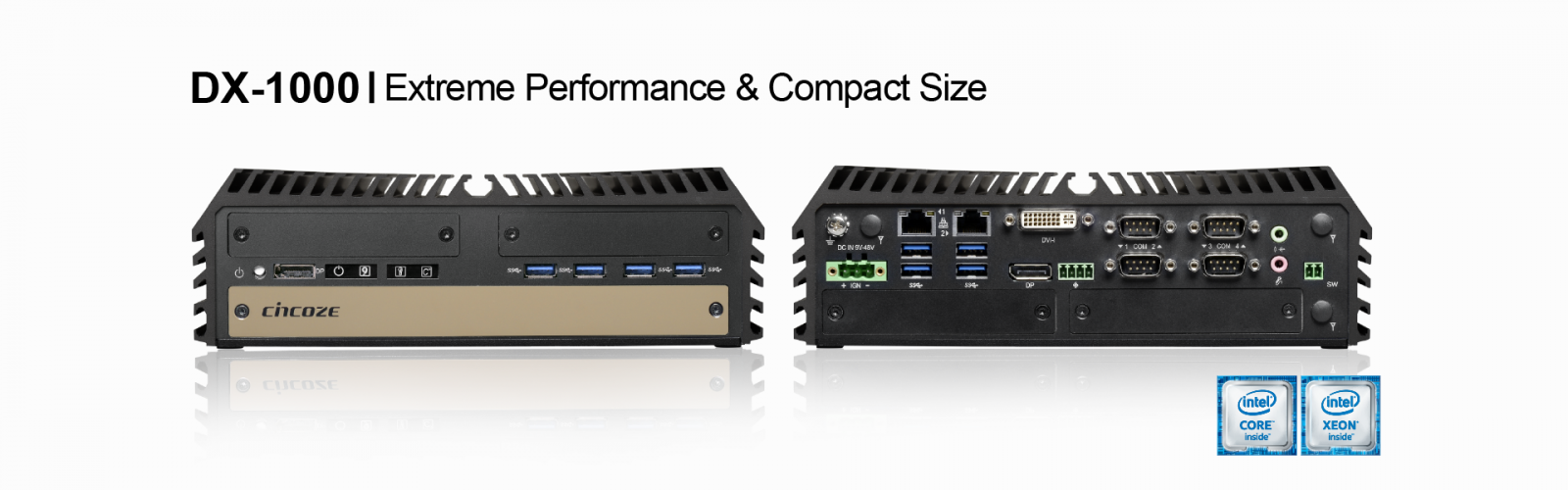
Cincoze, a global leader in embedded computing technology, today expands its product offering by introducing new rugged workstation “DX-1000”. The system is based on workstation grade Intel® C236 chipset to support 7th/6th Generation Intel® Xeon® E3 and Core™ Processors in LGA 1151 package. The DX-1000 Series can play 4K UHD content through Intel® Gen9 graphics engine with two DDR4 SO-DIMM sockets up to 32GB memory which delivers outstanding computing performance for high-end and multi-task applications.
The DX-1000 modular design is based onCincoze's exclusive CMI and CFM technologies, which offer a fast customer-specific solution without design risks or additional development costs. By supporting ready-to-use expansion modules such as 2x powered serial ports, 16x isolated digital I/O, 4x GbE M12/RJ45 LAN ports, PoE function and power ignition sensing, the DX-1000 Series allows users to configure their specific systems more efficiently.
The DX-1000 accommodates rich I/O interfaces, including 1x DVI-I, 2x DisplayPort, 2x Intel GbE LAN, 8x USB 3.0 and 4x BIOS-configurable RS-232/422/485 serial ports. In addition, 4x mini PCIe slots and 1x SIM socket are supported to empower the DX-1000 as a communication hub for a variety of wireless connections, such as GPS, Bluetooth, WiFi, and WWAN. With dual hot-swappable 2.5 SATA HDD/SSD drive bays and RAID 0/1 support, the system provides high data throughput or complete data redundancy.
“The DX-1000 is the last piece of the puzzle for our Diamond product line. DX stands for Diamond Extreme and it is specially designed for “workstation grade performance and compact size” within Cincoze’s product portfolio. Due to its application-driven design makes it ideal for factory automation, machine vision, in-vehicle computing and mobile surveillance. It’s also suitable for space-constrained applications and demanding environmental conditions.” said Brandon Chien, CEO of Cincoze.
The DX-1000 features wide operating temperature (-40~+70°C), wide range DC power input (9~48 VDC), high tolerance to vibration and shock (5/50 Grms), rugged uni-body construction, fanless, cable-less and jumper-less design to ensure a significantly prolonged lifespan and high system availability. The system also offers flexible mounting possibilities, including VESA mount, wall mount, DIN-rail mount and side mount options to fulfill various installation environments. And finally, the DX-1000 passed EN50155/50121-3-2 and E-mark certifications, making the system suitable for various industrial rolling stock and vehicle applications.
↧
Documentation for Atom x5-E3940
I am working on a new board-level system that will be used to demonstrate and provide proof-of-concept of an 'invention' (for lack of a better phrase) I've been fleshing out for a while. The nature of the invention is such that I need to interact with the signals coming into/out of the processor/SoC I use (i.e. very low level, physical signal level, not through software/firmware, which is why I can't use standard off-the-shelf boards). After evaluating several options, I have identified the Atom E3940 as the likely best fit solution for my needs. However, to do what I need to do I need to get the detailed technical information (databooks etc) and that requires privileged access--which I don't have. I'm not affiliated with a company at the moment, although the proof-of-concept will likely serve as the basis for a startup if all works out the way I want it to. :-) So my question is, how can I get access to the documentation I need? I'm more than willing to sign an NDA, I just don't know the process to use as an individual (not a company). When I called support they told me to post to this community so that's what I'm doing. Any help would be appreciated. Thanks!
↧
↧
Video: DO-254/DO-178 Safety Certifiable Mission Computer from HENSOLDT, Curtiss-Wright and CoreAVI

The Centrion DO-254/DO-178C Mission Computer was developed by HENSOLDT in partnership with Curtiss-Wright and CoreAVI. It provides interoperability, sensor integration, pilot assistance and the world’s first safety certifiable 4k video output. Centrion’s hardware, operating system, software drivers and development environment are fully integrated and the ready to use space is for your software development and testing.
Centrion customers can select from a variety of Curtiss-Wright COTS Intel and NXP processor cards, graphics and I/O modules.
Watch the video to learn more about the system.
Learn more about the products included in the system:
- The Centrion Mission Computer
- Curtiss-Wright Safety Certifiable SBCs
- Curtiss-Wright Safety Certifiable Graphics cards
- Curtiss-Wright Safety Certifiable I/O card
- CoreAVI Safety Certifiable drivers
- Wind River VxWorks 653 RTOS
↧
White Paper: The Root of Trust - A Foundation for Trusted Computing for Aerospace & Defense Applications
 Ensuring that an embedded system is trustworthy begins with the first instruction on trusted hardware. An effective trusted computing strategy for COTS solutions can include anti-tamper protection that guards against physical hardware intrusion, encryption techniques for critical data at rest, and effective cyberattack protections that ensure that a corrupted BIOS will not cause harm. The first step to ensure that the BIOS is not corrupted is to establish the hardware “Root of Trust.”
A foundational concept in cybersecurity, the Root of Trust establishes trusted functions, based on hardware validation of the boot process, to ensure that the system’s OS is being started up with uncorrupted code. These functions are located in hardware so they can’t be changed.
Protecting embedded systems against cyberattacks must start with the very first instruction that a processor executes. For Intel-based embedded hardware, two important weapons in the system designer’s trusted computing arsenal are Intel’s Trusted Execution Technology (TXT) and Boot Guard.
This paper looks at the growing demand for trusted computing solutions with effective protections against cyberattacks in the global defense electronics market. Download our White Paper to learn more about:
↧
Thermal Test Vehicle Question
Hi, we are looking for a thermal test vehicle to test the performance of thermal interface materials. Does anyone know if Intel sells TTV's or where I can obtain one for thermal management R&D?
↧